






Energy Storage Connection Solutions: Complete Guide to BESS Cables, Connectors, and Harness Design
The global energy transition is accelerating at an unprecedented pace. As renewable energy sources like solar and wind become mainstream, the need for reliable, efficient, and safe energy storage systems has never been greater. Battery Energy Storage Systems (BESS) are now deployed at every scale—from residential units to multi-gigawatt-hour utility installations—playing a critical role in grid stabilization, peak shaving, and renewable integration.
At the heart of every energy storage system lies an often-overlooked but mission-critical component: the connection infrastructure. Cables, connectors, busbars, and wire harnesses form the nervous system of BESS, carrying power and signals between battery modules, racks, inverters, and the grid. A single compromised connection can lead to system failure, thermal runaway, or costly downtime.
This comprehensive guide explores the full landscape of energy storage connection solutions—from battery module interconnects to grid-level DC cabling—covering key technologies, design principles, standards, and best practices for building safe and reliable BESS infrastructure.
What Are Energy Storage Connection Solutions?
Energy storage connection solutions encompass the complete range of electrical interconnect products and systems used to transfer power, data, and control signals within Battery Energy Storage Systems (BESS). These solutions span multiple voltage levels—from low-voltage cell monitoring circuits operating at 3–5V to high-voltage DC power transmission lines rated up to 1500V.
A complete energy storage connection system typically includes:
· DC power cables for battery rack and cluster connections
· High-current busbars for module-level power distribution
· Energy storage connectors with safety interlock features
· BMS (Battery Management System) communication and sensing cables
· Wire harnesses for battery pack internal wiring
· Manual service disconnect (MSD) connectors for maintenance safety
· Cable glands, conduits, and protective accessories
Unlike standard industrial cabling, energy storage connection products must operate reliably in demanding conditions—high DC voltages, elevated temperatures, chemical exposure from battery electrolytes, continuous charge-discharge cycling, and strict fire safety requirements. Selecting the right connection solution directly impacts system efficiency, safety, service life, and total cost of ownership.
Key Components of Energy Storage Connection Systems
A modern BESS installation involves multiple layers of electrical interconnection, each with distinct technical requirements. Understanding these layers is essential for system designers, integrators, and procurement professionals.
At the cell and module level, connections are characterized by low voltage but high current, requiring robust busbars, nickel-plated copper tabs, and precision welding techniques. The rack and cluster level introduces higher DC voltages (typically 800–1500V), where cable selection criteria include ampacity, voltage drop, insulation integrity, and fire resistance.
Beyond the DC side, AC connections link the Power Conversion System (PCS) output to step-up transformers and ultimately to the grid. Communication and auxiliary power cables run in parallel, connecting BMS units, sensors, cooling systems, and safety devices.

Battery Module Internal Connections
Inside each battery module, individual cells must be electrically connected in series and parallel configurations to achieve the desired voltage and capacity. These internal connections operate at relatively low voltages (3.2–48V) but can carry substantial currents, often exceeding 100A in large-format modules.
The primary connection methods for cell-level interconnects include:
· Laser-welded busbars: Aluminum or copper busbars welded directly to cell terminals, offering low contact resistance and high mechanical reliability. This method dominates in prismatic cell modules.
· Wire bonding: Aluminum wire bonds are commonly used in cylindrical cell packs, providing flexibility and vibration resistance.
· Flexible busbars: Laminated copper flex busbars accommodate thermal expansion and mechanical tolerance, critical for large-format modules where cell swelling can occur over thousands of cycles.
For applications requiring disassembly and serviceability, bolted connections with Belleville washers maintain consistent contact pressure across thermal cycling. Nickel-plated copper is the preferred material for busbars and terminals in lithium-ion systems, providing excellent conductivity while resisting corrosion from electrolyte vapors.
Low-voltage BMS sensing wires within the module must be routed separately from high-current paths to avoid electromagnetic interference. These typically use 22–26AWG conductors with FEP or XLPE insulation rated for 125°C continuous operation.
DC Power Cables for Battery Racks and Clusters

DC power cables form the backbone of energy storage system power distribution, carrying high-voltage DC electricity from battery racks to combiner boxes, and from combiner boxes to the PCS. These cables must be engineered for continuous operation at 1500V DC with temperature ratings up to 125°C.
Key considerations for DC cable selection in BESS applications:
· Conductor sizing based on continuous current rating with appropriate derating for bundle installation
· Voltage drop analysis ensuring less than 2% loss on DC circuits per IEC 60364 and NEC Article 706
· Insulation material selection: XLPO (cross-linked polyolefin) is preferred over standard XLPE for its superior thermal aging performance (3,000h at 125°C)
· Chemical resistance to battery electrolyte (LiPF6), cooling fluids, and fire suppression agents
· Flame retardancy meeting IEC 60332-3-22 Category A for bundled cable installations
Connectors and Interconnects in BESS
Energy storage connectors are purpose-built for the unique demands of BESS applications. Unlike generic industrial connectors, storage connectors must handle high DC voltages with positive locking mechanisms, touch-safe designs, and mechanical coding to prevent incorrect mating.
Current ratings span a wide range to accommodate different system scales:
· 60A–125A (6mm contact): Suitable for residential and small commercial storage systems, typically using 6–16mm² cable cross-sections
· 120A–250A (8mm contact): Common in commercial and industrial BESS installations, matching 16–70mm² cables
· 250A–350A (12mm contact): Used for medium to large-scale rack connections with 70–120mm² conductors
· 400A–500A (14mm+ contact): Reserved for high-power utility-scale applications requiring 120–240mm² cable cross-sections
Critical connector features in BESS environments include IP67 or IP6K9K ingress protection for outdoor container installations, High-Voltage Interlock Loop (HVIL) circuits that automatically disconnect power before connector separation, and 360-degree rotatable cable outlets for flexible installation routing. Orange-colored connector housings with mechanical keying have become the industry standard for visual identification of high-voltage DC circuits.
Manual Service Disconnect (MSD) connectors deserve special mention. These safety-critical components are rated for 350A–500A at 1500V DC and incorporate HVIL functionality. During maintenance, technicians can safely isolate battery racks by pulling the MSD, which breaks the HVIL circuit first, de-energizing contactors before the main power contacts separate.
Cable Standards and Certifications for Energy Storage
Compliance with international standards is non-negotiable in energy storage cable selection. Different markets demand different certifications, and using non-compliant cables can result in project delays, certification failures, or safety incidents.
The TÜV 2PfG 2693 standard has emerged as the most comprehensive BESS cable specification globally. It requires 3,000-hour thermal aging at 125°C, electrolyte chemical exposure testing, salt spray resistance (96 hours), UV exposure (1,000 hours), and mandatory halogen-free compliance per IEC 60754-1/2.
For the North American market, UL 9540 governs complete BESS system safety, while UL 4128 specifically addresses energy storage connector safety. NEC Article 706 provides installation requirements for energy storage systems, including cable ampacity, conduit fill, and spacing requirements.
In China, T/CNESA 1003-2020 specifies DC 1500V battery connection cables with requirements closely aligned to 2PfG 2693. IEC 62933-5-2 provides international system-level safety requirements for grid-integrated BESS installations.

Wire Harness Design for Battery Packs
Battery pack wire harness design is a specialized discipline that goes far beyond simple cable selection. Inside the confined spaces of a battery enclosure, harnesses must coexist with busbars, contactors, fuses, BMS circuit boards, thermal management systems, and structural components—all while maintaining strict electrical safety clearances.
Fundamental design principles for ESS wire harnesses include:
· Physical separation of HV and LV circuits: High-voltage power harnesses, interlock loops, communication cables, and sensor branches should never be bundled together. This separation reduces interference, improves assembly clarity, and enhances diagnostic efficiency.
· Creepage and clearance management: Required creepage distances depend on working voltage, pollution degree, and insulation material group (CTI value). These clearances must account for manufacturing tolerances, thermal expansion, vibration, and long-term aging—not just ideal CAD geometry.
· Bend radius control at transition points: Harness failures most commonly occur at connector exits, clamping points, bulkhead penetrations, and branch junctions. Each cable type demands its specified minimum bend radius, and strain relief features should be incorporated at all transition zones.
· Modular harness architecture: Dividing harnesses into logical functional modules (power sub-harness, BMS signal harness, interlock harness, sensor harness, external interface harness) enables isolated fault diagnosis, simplified field replacement, and reduced maintenance downtime.
Clear, consistent labeling with connector keying and color coding dramatically reduces the risk of misconnection during assembly and field service. The best designs make it immediately obvious which connector belongs where, even to a technician seeing the system for the first time.
Thermal Management and Fire Safety in Storage Cable Design
Fire safety is arguably the single most critical consideration in BESS cable design. A thermal runaway event in one battery module can cascade through an entire installation, and the cabling infrastructure plays a dual role—it must neither contribute fuel to a fire nor fail prematurely, disabling critical safety systems.
Essential fire safety requirements for BESS cables:
· Single-cable vertical flame test (VW-1 per UL 2556 or IEC 60332-1-2) is the minimum requirement for cables inside BESS enclosures
· Bundled cable flame propagation test (IEC 60332-3-22 Category A, 40-minute flame exposure) should be specified for main power cable trays in large installations
· Halogen-free construction (IEC 60754-1/2) is mandatory in European markets and increasingly required in North America
· Low-smoke emission (IEC 61034-2, Ds ≤ 150) reduces toxic fume hazards during fire events, protecting personnel and emergency responders
For critical safety circuits—including emergency shutdown loops, fire detection systems, and ventilation controls—fire-resistant cables tested to BS 6387 CWZ (withstanding 950°C flame for 3 hours, plus water spray and mechanical shock) should be considered. These cables must maintain circuit integrity long enough for safety systems to execute emergency protocols.
Ampacity derating is another essential thermal consideration. Cables installed in non-ventilated trays within BESS containers may require derating factors of 0.70–0.80 compared to free-air ratings. Container internal temperatures can exceed 50°C during peak operation, requiring additional temperature derating of 0.85–0.91 for every 10°C above the standard 30°C ambient reference.
Copper vs. Aluminum Conductors in Storage Applications
The conductor material decision has significant implications for system cost, weight, installation complexity, and long-term reliability. While copper has historically been the default choice for energy storage cables, aluminum solutions are gaining traction—particularly in large utility-scale projects where material cost and weight become dominant factors.
Copper conductors offer superior conductivity (approximately 61% higher than aluminum by volume), allowing smaller cross-sections for equivalent ampacity. They also provide better corrosion resistance, higher mechanical strength, and simpler termination. For applications where space is constrained or where reliability margins are tight, copper remains the preferred option.
Aluminum conductors, conversely, offer compelling advantages in weight reduction (approximately 50% lighter than equivalent copper) and material cost (typically 30–50% lower). For large BESS installations requiring hundreds of meters of DC cabling, these differences translate into substantial capital savings and easier cable handling during installation.
However, aluminum's adoption in energy storage requires careful engineering attention to connection technology. The formation of aluminum oxide on conductor surfaces can create high-resistance joints if not properly managed. Copper-to-aluminum transition connectors with bimetallic interfaces (using friction welding, explosion welding, or compression technology) are essential for reliable long-term performance at transition points. SUNKEAN has developed specialized Cu-Al transition solutions specifically optimized for energy storage applications, addressing the galvanic corrosion and thermal cycling challenges inherent in mixed-metal connections.
System-Level Considerations for Connection Design
Designing connection infrastructure for energy storage requires a system-level perspective that goes beyond individual component selection. Several cross-cutting factors influence the overall connection architecture:
· Installation efficiency: Pre-assembled cable harnesses with factory-terminated connectors can reduce on-site installation time by 40–60% compared to field-fabricated connections
· Maintenance accessibility: Critical disconnect points and frequently inspected connectors must be positioned with actual human access in mind, not buried under structural layers
· Scalability: Modular connection architectures allow BESS installations to expand from initial capacity without major rework of existing wiring
· Lifecycle cost: Premium BESS-rated cables (TÜV 2PfG 2693 certified) may cost 50–60% more upfront but eliminate replacement costs over a 25-year system life, delivering superior total cost of ownership versus economy-grade alternatives

Why SUNKEAN for Your Energy Storage Connection Needs
With the global energy storage market projected to exceed 500 GWh of annual installations by 2030, the quality and reliability of connection infrastructure has become a strategic differentiator for system integrators and project developers. SUNKEAN brings together deep domain expertise in cable manufacturing, connector technology, and wiring harness engineering to deliver integrated connection solutions for modern energy storage systems.
Comprehensive Product Portfolio
SUNKEAN's energy storage product range covers the complete BESS connection chain: high-voltage DC cables rated up to 1500V with XLPO insulation, UL-certified energy storage cables (UL 3817, UL 4128 compliant), pre-assembled battery pack wire harnesses, Cu-Al transition connectors for mixed-metal installations, PV and storage hybrid cables, and custom-engineered connection solutions for specialized applications.
Manufacturing Excellence
Our manufacturing facilities are equipped with Rosendahl foaming extrusion lines, SIKORA online monitoring systems for real-time dimensional control, and 67GHz network analyzers for high-frequency verification. Electron-beam crosslinking technology ensures consistent XLPO insulation properties, verified through 3,000-hour thermal aging tests at 125°C in accordance with TÜV 2PfG 2693 requirements.
Global Compliance
SUNKEAN energy storage cables carry international certifications including TÜV, UL, CE, and IEC standards, ensuring compliance with project requirements across European, North American, Middle Eastern, and Asia-Pacific markets. Our technical team provides full documentation support—from material declarations and test reports to installation guidelines—streamlining the certification process for system integrators.
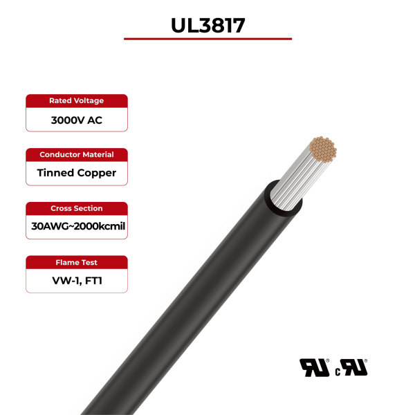
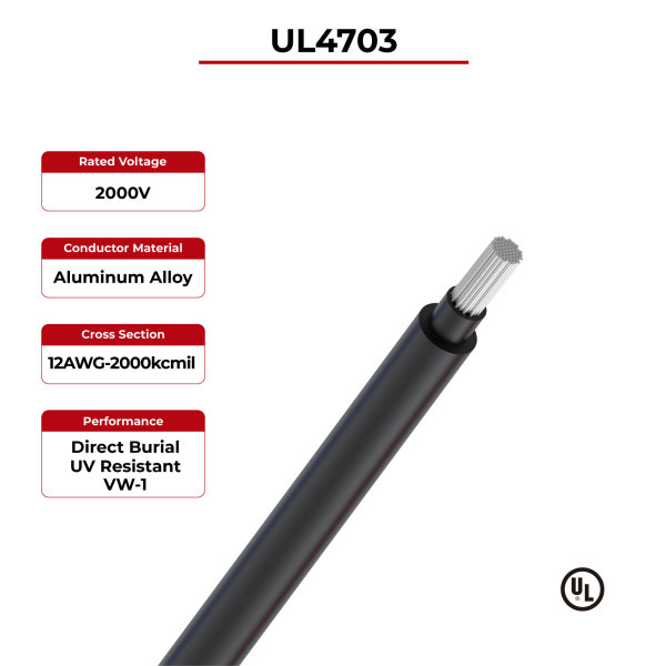
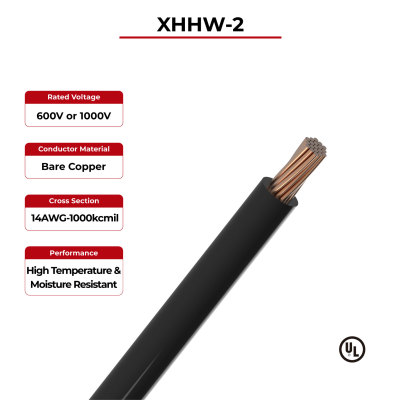
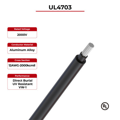
Conductor: 18AWG~2000kcmil
Color: Black, red or other colors
Color: Black, red or other colors
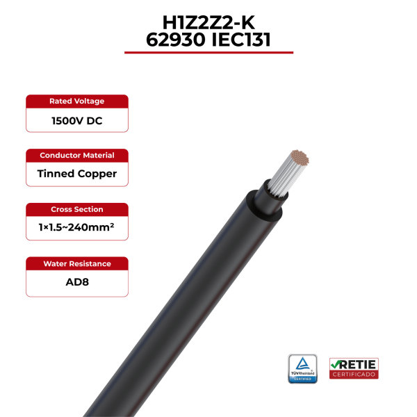
Conductor: 1×1.5~400mm²
Insulation Color: Optional color
Jacket Color: Optional color
Insulation Color: Optional color
Jacket Color: Optional color
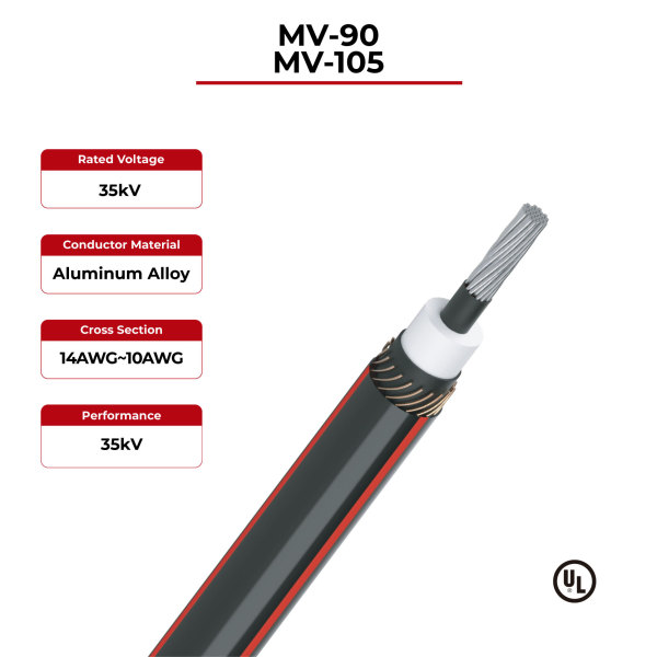
Conductor: 14AWG~2000kcmil
Insulation Color: White
Jacket Color: Black & red
Insulation Color: White
Jacket Color: Black & red
Energy storage connection solutions represent far more than a bill of materials line item—they are fundamental to system safety, performance, and long-term economic viability. From cell-level interconnects to grid-tie cables, every connection point must be engineered with careful attention to electrical, thermal, mechanical, and chemical requirements.
As energy storage systems grow in scale and complexity, the value of integrated connection solutions from experienced manufacturers becomes increasingly clear. Pre-engineered cable assemblies, certified BESS-rated cables, and application-specific connector systems not only reduce project risk but also accelerate deployment timelines and improve total lifecycle economics.
For project developers, EPC contractors, and system integrators building the next generation of energy storage infrastructure, partnering with a knowledgeable connection solutions provider is an investment in reliability, safety, and long-term performance.
Looking for reliable energy storage cable and connection solutions for your BESS project?
SUNKEAN provides high-performance energy storage cables, battery pack wire harnesses, and Cu-Al transition solutions designed for utility-scale, commercial, and industrial BESS applications — with proven durability, international certifications, and global project experience.
👉 Contact our team for technical consultation or product recommendations,
or simply send us your project requirements:
Email: sales@sunkean.com
Tel: +86 0510-81083036
WhatsApp: 17252867971