Power Distribution
The world runs on cables most people never see. Between the substation and the wall outlet, between the solar array and the inverter, between the battery rack and the grid — medium and low voltage distribution cables carry the load. Select the wrong cable and you get voltage drop that starves equipment, insulation that fails after five years instead of thirty, or a fire code violation that halts commissioning.
Distribution cable selection isn't glamorous, but it's where electrical engineering meets the real world. A correctly sized XLPE-insulated aluminum cable buried two meters underground will outlast the building it serves. A poorly chosen cable in the same trench will need replacement within a decade — if it doesn't fail first.
This guide covers the engineering decisions behind medium and low voltage distribution cable selection: voltage classes, conductor materials, insulation types, sizing methodology, installation methods, and the standards that govern them all.
Defining the Voltage Classes
Distribution cables fall into two categories, and confusing them is the first mistake many projects make:
| Class | Voltage Range | Typical Applications |
|---|
| Low Voltage (LV) | Up to 1 kV AC (1.5 kV DC) | Building wiring, branch circuits, solar string cables, EV charging, battery racks |
| Medium Voltage (MV) | 1 kV to 35 kV AC | Primary distribution feeders, wind farm collection grids, industrial plant supply, solar inverter-to-transformer runs |
The distinction matters because MV and LV cables are built differently. MV cables require metallic screening layers to manage electric field distribution, thicker insulation to withstand higher dielectric stress, and specialized termination hardware that costs 5-10x more than LV equivalents. An MV cable used where LV would suffice wastes money. An LV cable used where MV is required is a safety hazard.
Rule of thumb: If the system voltage exceeds 1 kV AC, you need MV-rated cable with semiconducting screens — not just thicker insulation. The screen layers distribute the electric field uniformly and prevent partial discharge at the conductor-insulation interface, which is the leading cause of premature MV cable failure.
Cable Construction: Layer by Layer
A modern distribution cable is an engineered stack of materials, each serving a specific function:
Conductor
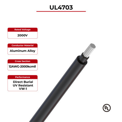
The conductor carries the current. In distribution cables, it's almost always either copper or aluminum, stranded per IEC 60228 Class 2 for fixed installations or Class 5 for flexible applications. The choice between copper and aluminum is one of the most consequential decisions in cable engineering. Copper offers higher conductivity and smaller cross-section for the same ampacity, but aluminum costs less and weighs roughly one-third as much, making it the default for long distribution runs.
Insulation
Insulation prevents current from leaking outside the conductor. The dominant materials are:
- XLPE (cross-linked polyethylene): Rated for 90°C continuous operation, 250°C short-circuit. The industry standard for both MV and LV distribution since the 1990s. Resistant to moisture, most chemicals, and aging.
- EPR (ethylene propylene rubber): Also rated for 90°C, but more flexible than XLPE and better suited to repeated bending. Common in industrial and mining applications where cables are moved during operation.
- PVC (polyvinyl chloride): Rated for 70°C. Low cost, adequate for indoor LV applications, but releases toxic halogen gases when burned — increasingly restricted in public buildings and transit tunnels.
Metallic Screen (MV Only)
For cables rated above 1 kV, a metallic screen — typically copper tape or concentric copper wires — wraps the insulation to contain the electric field and provide a path for fault currents. Skip this layer on MV cables and the electric field will concentrate at imperfections in the insulation, causing partial discharge that erodes the dielectric until breakdown occurs.
Armor
Steel wire or steel tape armor provides mechanical protection for direct-buried and cable-tray installations. Armor is optional for LV indoor cables but essential for any cable buried underground or installed in environments where impact damage is possible. For single-core AC cables, non-magnetic aluminum armor is used instead of steel to prevent eddy current losses.
Outer Jacket
The jacket protects the cable from environmental damage: UV radiation, moisture, chemicals, and abrasion. Common jacket materials include PVC (general purpose), PE (underground and outdoor), LSZH (low-smoke zero-halogen for transit and public buildings), and PUR (industrial applications requiring oil and abrasion resistance).
Sizing Cables: Beyond the Ampacity Table
Every cable manufacturer publishes ampacity tables — lookup charts that tell you the current-carrying capacity for a given conductor size and installation condition. These tables are starting points, not final answers. Real-world cable sizing requires four calculations:
| Sizing Check | What It Ensures | Failure Mode If Skipped |
|---|
| Ampacity (continuous current) | Conductor temperature stays within insulation rating | Insulation degradation, premature failure |
| Voltage drop | Load receives adequate voltage | Motor undervoltage, equipment malfunction, efficiency loss |
| Short-circuit withstand | Cable survives fault current until breaker trips | Cable destruction during first fault event |
| Economic optimization | Lifetime energy losses balanced against material cost | Higher operating cost over 30-year service life |
The most commonly skipped check is voltage drop. A 95mm² aluminum cable might carry 200A according to the ampacity table, but over a 200-meter run at 400V three-phase, the voltage drop exceeds 4% — beyond the 3% limit most distribution standards specify for equipment terminals. The fix is simple: increase the conductor cross-section, but only if someone does the calculation.
Derating factors reduce the base ampacity to account for real-world conditions:
- Ambient temperature: For every 5°C above the base temperature (usually 30°C for air, 20°C for ground), reduce ampacity by approximately 5%
- Grouping: Multiple cables touching or in the same conduit heat each other. Six cables in a single layer require a 0.72 derating factor
- Thermal insulation: Cables passing through building insulation lose their ability to dissipate heat. Derating can be 50% or more
- Soil thermal resistivity: Dry soil around direct-buried cables can have 2-3x higher thermal resistance than moist soil, requiring larger conductors in arid climates
Installation Methods: The Method Shapes the Cable
The installation method isn't just about routing — it determines what cable construction you need:
Direct Burial
Cables buried underground need armor for mechanical protection and moisture-resistant jackets (PE or MDPE). Minimum burial depth is typically 0.6m for LV and 0.8m for MV. Thermal backfill may be required in poor soil conditions. The cable must withstand ground moisture, freeze-thaw cycles, and occasional excavation damage. Solar distribution cables are commonly direct-buried between string arrays and combiner boxes.
Cable Trays
Tray installations dominate industrial and commercial buildings. Cables on trays must be sunlight-resistant if outdoors and rated for the tray's ambient temperature. The advantage is maintainability — cables are accessible for inspection, modification, and replacement. In energy storage systems, cable trays are standard for routing DC cables between battery racks and power conversion systems.
Conduit
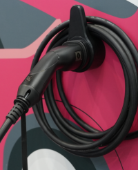
Rigid or flexible conduit provides physical protection while allowing cable replacement. Conduit fill calculations limit the cable cross-section to 40% of the conduit's internal area for a single cable. Conduit installations are common in commercial buildings and for EV charging infrastructure, where charging cables transition between the dispenser and the grid connection point.
Aerial
Overhead distribution uses self-supporting cables (ABC — aerial bundled cable) or individual conductors on poles. Aerial cables must withstand UV exposure, wind loading, ice accumulation, and temperature extremes from -20°C to +70°C. Aluminum conductors dominate aerial installations because the weight savings over copper reduces pole loading by 60%.
Standards and Compliance
Distribution cable standards define construction requirements, test methods, and installation practices. Specifying the right standard ensures the cable will perform as expected and pass inspection:
| Standard | Scope | Key Requirements |
|---|
| IEC 60502-1 | LV power cables up to 1 kV | Construction, dimensions, test methods for XLPE and PVC insulated cables |
| IEC 60502-2 | MV power cables 6 kV to 30 kV | Additional requirements for screening, insulation thickness, partial discharge testing |
| NEC Article 310 (NFPA 70) | US conductor sizing and installation | Ampacity tables, derating rules, conductor temperature ratings |
| IEC 60332-1 / -3 | Flame retardancy | Vertical flame propagation testing for single cables and cable bunches |
| EN 50575 (CPR) | Fire performance of construction products | Euroclass ratings Aca to F2ca for cables in EU buildings |
| IEC 60228 | Conductor classes | Defines Class 1 (solid), Class 2 (stranded), Class 5 (flexible) conductor constructions |
|---|
CPR compliance note: Since July 2017, all power cables sold in the European Union for permanent installation in buildings must carry a Declaration of Performance (DoP) and a CE mark under EN 50575. The fire performance class (Aca, B1ca, B2ca, Cca, Dca, Eca, F2ca) must match the building's risk category. Specifying a cable without CPR classification for an EU project is a regulatory violation.
Application-Specific Selection
Solar and Photovoltaic Distribution
Solar farms generate power at DC voltages up to 1500V, which then passes through inverters to become AC for grid connection. The DC side requires cables rated for UV exposure, extreme temperatures (-40°C to +90°C), and potential moisture ingress. Solar DC cables are typically XLPE-insulated, halogen-free, and certified to TUV 2 PfG 2693 or EN 50618 standards. At the AC side, standard LV distribution cables connect the inverter to the transformer, while MV cables handle the collection grid between transformer stations.
Energy Storage Systems
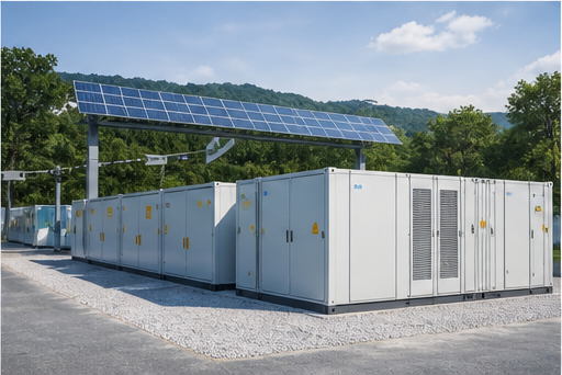
Battery energy storage systems present unique cable challenges: high DC currents (500-2000A per rack), frequent charge/discharge cycling, and thermal management at connection points. BESS DC cables must be specifically rated for DC voltage — DC arcs don't self-extinguish at zero-crossings like AC arcs do, so DC-rated insulation is thicker and tested differently. Cable cross-sections of 95mm² to 240mm² are common for rack-to-PCS connections, with flame-retardant and low-smoke requirements for enclosed container environments.
EV Charging Infrastructure
EV charging stations bridge the distribution grid to the vehicle. Level 2 AC chargers use LV cables rated for 32-80A continuous duty. DC fast chargers (50-350 kW) pull 125-500A from the grid at 480V, requiring dedicated MV or LV cable runs sized for continuous maximum load. Cable insulation must withstand the thermal cycling that occurs when a charger transitions from idle to full output multiple times per day.
Industrial Facilities
Industrial distribution often involves mixed-voltage environments: MV feeders from the utility to the plant's main transformer, then LV distribution to motors, lighting, and process equipment. Industrial cables face chemical exposure, mechanical stress, and higher ambient temperatures. XLPE insulation dominates industrial LV applications, while MV feeders use either XLPE or EPR-insulated cables with armor for mechanical protection in cable trays and trench systems.
Frequently Asked Questions
What's the difference between XLPE and PVC insulation for LV cables?
XLPE is rated for 90°C continuous operation versus PVC's 70°C, giving XLPE approximately 15-20% higher ampacity for the same conductor size. XLPE is also more resistant to moisture, aging, and short-circuit temperatures (250°C vs 160°C). PVC is cheaper and easier to terminate, but its halogen content makes it unsuitable for enclosed public spaces. For any new installation expected to last more than 15 years, XLPE is the better investment.
When should I choose aluminum over copper conductors?
Aluminum is the default choice when weight and cost matter: long distribution runs, aerial installations, and large cross-sections (above 95mm²). Copper is preferred when space is limited (switchgear connections, compact equipment), when mechanical flexibility is needed (flexing applications), and when corrosion resistance is critical (marine environments). For any aluminum installation, use bimetallic transition connectors when connecting to copper terminals to prevent galvanic corrosion.
How do I calculate voltage drop for a three-phase cable run?
The simplified formula is: ΔV = √3 × I × L × (R cos φ + X sin φ), where I is the load current, L is the cable length, R is the AC resistance per meter, X is the reactance per meter, and cos φ is the power factor. For practical purposes, a 3% voltage drop limit means a 95mm² aluminum cable can run roughly 150 meters at 200A, 400V three-phase before exceeding the limit. Online calculators are acceptable for preliminary sizing, but final design should reference manufacturer data sheets for exact resistance values.
What fire performance class do I need for cables in a commercial building?
It depends on the building's classification under local fire codes. In the EU, EN 50575 defines classes from Aca (highest) to F2ca (lowest). Most commercial buildings require at least Class Cca (flame retardant, low smoke, low flaming droplets). High-rise buildings, hospitals, and transit hubs typically require Class B2ca or higher. In the US, NEC requirements specify plenum-rated (CMP) or riser-rated (CMR) cables depending on the installation location.
Can LV and MV cables share the same trench?
Yes, but with segregation. Most codes require a minimum 150mm separation between LV and MV cables in the same trench, or a physical divider. The concern is both electrical (induced voltages in LV cables from MV fault currents) and practical (preventing damage to LV cables during MV cable maintenance). In practice, using separate conduits or placing MV cables in a lower layer with a concrete or brick divider is the standard approach.
Getting Cable Selection Right
Distribution cable selection is a decision that lasts decades. A correctly specified cable will serve its full design life — typically 30 years for XLPE-insulated underground cables — with minimal maintenance. A poorly specified cable will need replacement, cause voltage problems, or create safety hazards long before its expected end of life.
The fundamentals are straightforward: match the voltage class to the system, choose insulation rated for the operating temperature and environment, size the conductor for ampacity and voltage drop under real-world conditions, select an installation method that protects the cable, and specify standards that match the regulatory environment. Do this, and the cable you bury today will still be delivering power when the next generation of engineers is specifying its replacement.